


 Eng
Eng 
 русский

Gland Packing Guide: Mechanics, Sizing, and Globe Valve Installation
 2026.05.25
 Industry News
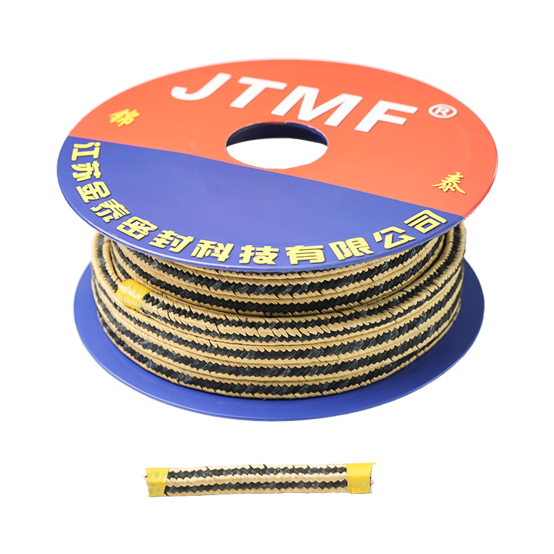
Gland packing provides a dynamic pressure seal around rotating or reciprocating shafts and valve stems through controlled mechanical deformation. By tightening the gland follower, axial compressive force is converted into radial pressure against the moving stem and stationary stuffing box wall. This engineered friction restricts process fluid leakage to a controlled, microscopic level required for heat dissipation, while maintaining system pressure integrity.
How Gland Packing Works: The Mechanics of Radial Sealing
The operational physics of a braided fiber packing ring rely on the transmission of fluid pressure and mechanical axial loading. When the gland nuts are tensioned, the gland follower pushes downward into the stuffing box cavity. The packing material deforms laterally, filling the microscopic voids between the moving valve stem (or pump shaft) and the structural bore wall.
In dynamic pumping applications, a completely dry seal causes rapid thermal degradation and frictional failure. Therefore, the material is engineered to allow a minute, controlled leakage rate—typically 20 to 60 drops per minute for slurry or chemical pumps—to act as a natural coolant and lubricant. In static or slow-cycling valve stems, specialized materials like flexible graphite or PTFE allow for drop-tight sealing profiles under high operating pressures.
How to Calculate Gland Packing Size
Installing an incorrect cross-sectional packing profile leads to premature failure, extrusion, or total loss of sealing capability. The correct dimensional size must be determined by calculating the physical clearance distance between the internal diameter of the stuffing box bore and the outer diameter of the valve stem or pump shaft.
To compute the cross-sectional packing width required, utilize the following structural formula:
Packing Size = (Stuffing Box Inner Diameter - Valve Stem Outer Diameter) / 2
Consider a concrete practical calculation example from an industrial application:
| Measured Parameter | Physical Value (Metric) | Physical Value (Imperial) |
|---|---|---|
| Stuffing Box Inner Diameter (Bore) | 38.00 mm | 1.500 inches |
| Valve Stem Outer Diameter (Shaft) | 26.00 mm | 1.023 inches |
| Total Dimensional Difference | 12.00 mm | 0.477 inches |
| Calculated Target Packing Size | 6.00 mm (Select 6mm Square) | 0.238 inches (Select 1/4 inch Square) |
How to Change Gland Packing of a Globe Valve
Replacing old, hardened packing configurations within a globe valve requires a systematic approach to prevent scoring the highly finished surface of the valve stem. Follow this precise mechanical sequence during plant turnarounds or maintenance cycles:
- Isolation and Pressure Depressurization Isolate the inline piping grid entirely. Open the globe valve to its fully open back-seat position if working under inline conditions, or completely depressurize the system and actuate the valve to a mid-travel state to ensure no trapped process line pressure remains within the bonnet cavity.
- Disassembly of Gland Componentry Loosen the gland follower nuts evenly on both sides of the yoke. Flip the gland eye-bolts clear and slide the gland follower up the valve stem to fully expose the top layer of the old packing stack inside the stuffing box chamber.
- Extraction of Degraded Packing Rings Insert a specialized flexible corkscrew packing extraction tool into the stuffing box. Thread the tool point into the center of each ring and pull outward. Repeat this sequence until all degraded rings, including any underlying lantern rings or spacer bushings, are extracted. Clean the chamber bore completely using an air line or soft solvent flush.
- Precision Ring Cutting and Joint Prepping Wrap the new packing coil tightly around a mandrel or a spare valve stem of identical diameter. Using a razor-sharp blade, cut individual rings at a precise 45-degree skive angle. Skive joints provide a superior overlapping thermal expansion seal compared to simple 90-degree straight butt joints.
- Staggered Ring Installation and Torque Seating Install each ring into the stuffing box individually. Use a split-tamping sleeve or the gland follower to push each ring firmly to the bottom of the cavity. Stagger the skive joints of adjacent rings by exactly 90 to 120 degrees to eliminate a direct linear path for potential leak migration. Tighten gland follower nuts by hand, then apply final mechanical torque increments until optimal stem resistance is established.

 Home
Home +86 152 4020 4398
 zdjt004@jsjtmf.vip
 No.2 Xingyuan East Road, Yuanzhu Town Industrial Park, Taixing City, Jiangsu Province, China
Copyright © 2024. Jiangsu Jintai Sealing Technology Co., Ltd. All rights reserved. Custom Sealing Gaskets, Sealing Packing, Rubber Products
